Projections and Views Engineering Design - McGill University
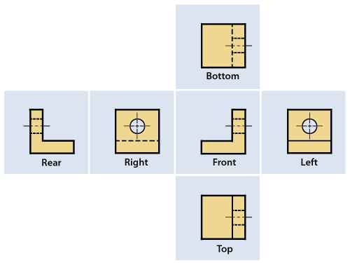
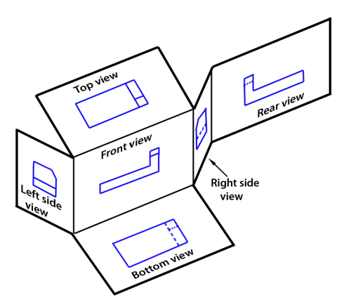
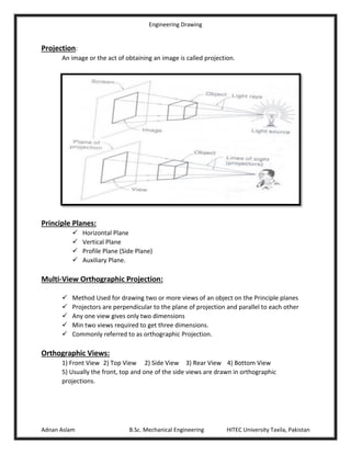
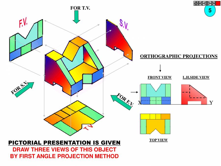
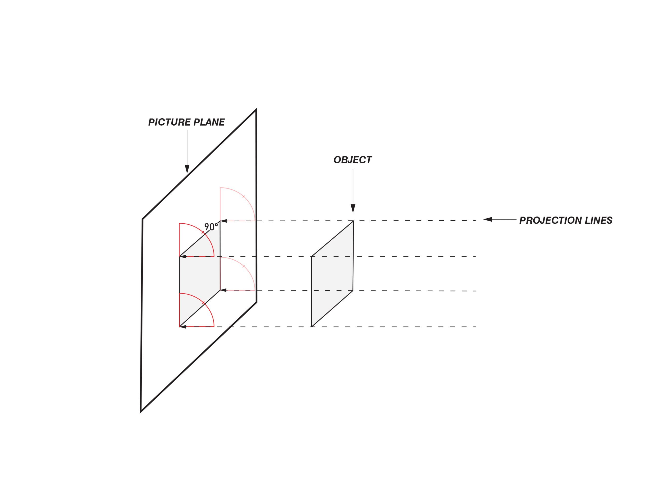
A three-dimensional object can be represented in a single plane, such as on a sheet of paper, using projecting lines and planes. All projection theory is based on two variables: line of sight (projecting lines) and plane of projection. A line of sight (LOS) is an imaginary line between an observer’s eye and an object. A plane of projection (i.e., an image or picture plane) is an imaginary flat plane upon which the image is projected. The projection is produced by connecting the points where the lines of sight pierce the projection plane. As a result, the 3D object is transformed into a 2D view. If the distance from the observer to the object is infinite, then the projection lines are assumed to be parallel, and the projection is called a parallel projection. Parallel projection is orthographic if the plane of projection is placed between the observer and the object, and the plane is perpendicular to the parallel lines of sight. You can use parallel projection technique to create both multiview and pictorial (isometric and oblique) views. In multiview orthographic projection (see details below), the object surface and the projection plane are parallel, and you can see only two dimensions. In isometric view (orthographic) the surface is no longer parallel to the projection plane, but the latter is perpendicular to the lines of sight, with three dimensions being seen. In oblique projection (non-orthographic) the object surface and the projection plane are also parallel, but the lines of sights are not perpendicular to the projection plane, and you can see again three dimensions. If the distance from the observer to the object is finite, then the projection lines are not parallel (since all lines of sight start at a single point), and the drawing is classified as a perspective projection. In perspective view the object surface and projection plane can be also parallel. Multiview projection By changing position of the object relative to the line of sight you can create different views of the same object. Drawing more than one face of an object by rotating the object relative to your line of sight helps in understanding the 3D form. Having several views on one drawing you use the concept of multi-view projection, which is based on the orthographic (parallel) projection technique where the plane of projection is positioned between the observer and the object, the plane of projection is perpendicular to the parallel lines of sight, and the object is oriented such that only two of its dimensions are shown. Main principles of creating multiview projections The plane of projection can be oriented to produce an infinite number of views of an object. However, the most common views are the six mutually perpendicular views that are produced by six mutually perpendicular planes of projection: Front view – the one that shows most features or characteristics. Left side view – shows what becomes the left side of the object after establishing the front view position. Right side view – shows what becomes the right side of the object after establishing the front view position. Top view – shows what becomes the top of the object once the position of the front view is established. Bottom view – shows what becomes the bottom of the object once the position of the front view is established. Rear view – shows what becomes the rear of the object once the position of the front view is established. The most informative (descriptive) view of the object to be represented is normally chosen as the principal view (front view). This is view A related to the corresponding direction of viewing A and it usually shows the object in the functioning, manufacturing, or mounting position. View positions on drawings and corresponding viewing directions Positions of the other views relative to the principal view in the drawing depend on the projection method. The number of views and sections must be limited to the minimum necessary to fully represent the object without ambiguity. Unnecessary repetition of details must be avoided. Conventional view placement Generally, three views of an object are enough, however, a drawing must contain as many views as necessary to illustrate the part, usually at right angles to one another. Frontal plane of projection In multiview projection, the object is viewed perpendicular to the main faces, so that only one face of the object is depicted in each view. The frontal plane of projection is the plane onto which the front view of a multiview drawing is projected. In the front view you can see height and width of the object, but you cannot see its depth. Horizontal plane of projection The top view is projected onto the horizontal plane of projection, which is plane suspended above and parallel to the top of the object. The top view of an object shows the width and depth dimensions. Profile plane of projection In multiview drawings, the right side view is the standard side view. The right side view is projected onto the right profile plane of projection, which is a plane that is parallel to the right side of the object. However, you can also use the left side view if it is more descriptive and informative. Moreover, when needed, you can include both side views into one drawing. The side view of an object shows the depth and height dimensions. The three-view multiview drawing is the standard used in engineering and technology, because often the other three common views are mirror images and do not add to the knowledge about the object. The standard views used in a three-view drawing are the top, front, and right side views, arranged as shown in the figure: The width dimension is common to the front and top views. The height dimension is common to the front and side views. The depth dimension is common to the top and side views. For simple parts one or two view drawings will often be enough. In one-view drawings the third dimension may be expressed by a note, or by descriptive words, symbols, or abbreviations, such as Ø, HEX, etc. Square sections may be indicated by light crossed diagonal lines, as shown above, which applies whether the face is parallel or inclined to the drawing plane. Another example of a one-view drawing: Additional views may be added if they improve visualization. The views should also be chosen to avoid hidden feature lines whenever possible. That means that the most descriptive view should be shown. Besides, you should select the minimum number of views needed to completely describe an object. Eliminate views that are mirror images of other views. Why multiview drawings technique is so important? To produce a new product, it is necessary to know its true dimensions, and true dimensions are not adequately represented in most pictorial drawings. For example, the photograph is a pictorial perspective image. However, as you can see, the image distorts true distances, while the latter are essential for manufacturing and construction, and in this example the case in question is the width of the road, not the electrical pole! In mechanical engineering perspective projections distort measurements. As you can see, the two width dimensions in the front view of the block appear different in length in the perspective projection. In other words, equal distances do not appear equal on a perspective drawing. Thus, since engineering and technology depend on exact size and shape descriptions for design, the best approach is to use the parallel projection technique (orthographic projection) to create multi-view drawings where each view shows only two of the three dimensions (width, height, depth). To summarize: The advantage of multiview drawings over pictorial drawings is that multiview drawings shows the true size and shape of the various features of the object, whereas pictorials distort true dimensions which are critical in manufacturing and construction. 1st & 3rd angles (glass box) What exactly you should place on the right side projection? Is it that we can see from the left side, or from the right side of the object? To answer these questions there are two different ways, based on two different principles First-Angle Projection Third-Angle Projection. Third angle is used in Canada and the United States. First angle is used in Europe. In third angle orthographic projection the object may be assumed to be enclosed in a glass box. Each view represents that which is seen when looking perpendicularly at each face of the box. The resulted views are identified by the names as shown. The front, rear, and side views are sometimes called elevations, e.g., front elevation. The top view may be termed the plan. If desired, the rear view may be shown both ways – at the extreme left or the extreme right. When this is not practical to show rear view at he extreme left or right due to the length of the part, particularly with panels and mounting plates, the rear view should not be projected up or down, as this would result in its being shown upside down. Instead, it should be drawn as if projected sideways, but located in some other position, and should be clearly labelled REAR VIEW REMOVED. In first angle orthographic projections the object is considered as being rolled over to either side, so that the right side of the object is drawn to the left of the front elevation: It is mandatory to indicate the method of multiview projection by including the appropriate ISO (International Organization for Standardization) projection symbol – the truncated cone: You should place this symbol in the lower right-hand corner of the drawing in or adjacent to the title block. Axonometric projection It is one of the pictorial drawing projections, which are useful for illustrative purposes, educational aids, installation and maintenance drawings, design sketches, and the like. The Greek word axon means axis and metric means to measure. Axonometric projection is a parallel projection technique used to create a pictorial drawing of an object by rotating the object on an axis relative to a plane of projection. Axonometric projections such as isometric, dimetric, and trimetric projections are orthographic, in that the projection lines are all parallel, but the angle of views is so chosen that three faces of a rectangular object would be shown in a single view. Axonometric drawings are classified by the angles between the lines comprising the axonometric axes. The axonometric axes are axes that meet to form the corner of the object that is nearest to the observer. When all three angles are unequal the drawing is classified as a trimetric. When two of the three angles are equal the drawing is classified as a dimetric. When all three angles are equal the drawing is classified as a isometric. Although there are an infinite number of positions that can be used to create such a drawing only few of them are used. Enlarged detail To eliminate the crowding of details or dimensions, an enlarged removed view may be used. The enlarged view should be oriented in the same manner as the main view, the scale of enlargement must be shown, and both views should be identified by one of the methods shown in the illustrations – with the leader line or with the circle line. The circle enclosing the area on the main view should be drawn with a thin line.
Projections and Views Engineering Design - McGill University

Orthographic projection - Technical drawing - Engineering drawing
Basics Of Engineering Drawing (Dimensioning,Projections,Principle

McGill University Power Plant / FABG

zhen yang - McGill University

Orthographic projection in engineering drawing

Topic 2 - Formats & Title Block, PDF
ENGINEERING DRAWING _ I.B.TECH (ALL BRANCHES) - PowerPoint Slides

The McGill New Vic Project - ERA Architects

first angle and third angle projection –

Created a new, fully functioning Object Classification System with, scp foundation classifications
Moshe Safdie donates his archive and Habitat 67 unit to McGill

Lemay Unites Architecture, Art and Landscape Design at Place des
VISUAL GLOSSARY – Axo Demystified